zaterdag 11 maart 2017

A cheap STM32 LORA node


See:

https://www.thethingsnetwork.org/labs/story/a-cheap-stm32-arduino-node

zaterdag 24 december 2016

An ESP8266 scrolling display with a 5x8 WS2812 matrix


See https://github.com/tomtor/ESP-8266 for the LUA code (loaded on the ESP-8266) and the python driver with the fonts.

zondag 7 februari 2016

The SIMH PDP11 and VAX simulator

This weekend I made a nostalgic trip back in time by recreating the computer environment I used at the university in 1982 and later.

The Computer History Simulation Project created the SIMH emulator (https://github.com/simh/simh) which I used to simulate a PDP11/70 and a VAX 780. On the PDP11/70 I loaded the original Unix v7 tapes and on the Vax I loaded BSD4.1 and BSD4.3.

http://gunkies.org/wiki/Installing_4.3_BSD_on_SIMH describes the procedure step by step, but states that the networking does not work.

I used the latest version of SIMH from Github (4.0 beta) and figured out how to get the Ethernet running on the Vax 780.

The trick is to add:

set xu enable
attach xu msk0

to your boot.ini file.

You should replace msk0 by the name of your physical netwerk interface, eg eth0 on your Linux machine, and start it with sudo vax780 boot.ini

See https://github.com/simh/simh/blob/master/0readme_ethernet.txt for details and other configuration options.

The last step is to rebuild the kernel, you need to add

device          de0     at uba? csr 0174510     vector deintr

to /usr/sys/conf/GENERIC and rebuild the kernel:

bsd43# cd /usr/sys/conf
bsd43# config GENERIC
Don't forget to run "make depend"
bsd43# cd ../GENERIC
bsd43# make depend
...
bsd43# make
...
bsd43# cp vmunix /

create a /etc/resolv.conf with:

nameserver 8.8.8.8

reboot, and you can FTP and telnet to every host on the Internet with software which was compiled in 1986. Amazing isn't it?!

As an exercise I changed the date.c program because it would not let me set a date after 1999, and I changed the timezone to 0 in GENERIC, but after those changes the clock/calendar are OK.

bsd43# date
Sun Feb  7 20:31:58 WET 2016
bsd43#

I also fixed the printing of the man pages so they don't show as year 116 ;-)

Finally I created a program to convert the simulated tapes to normal files, an adaption of
http://zazie.tom-yam.or.jp/starunix/mktape.c which works the other way around.

Get it from my Raspberry Pi-1 running FreeBSD 11-current:


donderdag 31 december 2015

FreeBSD video console (vidconsole) on the Raspberry Pi

In the default configuration with FreeBSD on the Raspberry console messages are written on the serial console.

After a "shutdown now" one cannot enter commands from a connected USB keyboard.

I tried to enable the video console but adding

console="vidconsole" 

to /boot/loader.conf just results in an error message from the bootloader.

Adding:

kern.console="ttyv0"

to /etc/sysctl.conf does the trick!

Note that one still cannot enter input for the bootloader in the early boot stages. I have not found a solution for that issue (probably needs different options for UBLDR), you will have to use a serial console for now.

woensdag 23 december 2015

Booting a Freebsd image on a usb stick with the Raspberry Pi

It took me some time to figure out how to do this, but it's actually very simple.

Create an USB stick (or disk) with the Freebsd image you want to boot and connect it to a USB port on your Pi.

Create a small standard Freebsd image on a small SD-card and place it in the Raspberry SD slot.

Boot it and create as superuser the file:
/boot/loader.conf
with the following content:
currdev=disk0s2a
vfs.root.mountfrom="ufs:/dev/da0s2a"
Now reboot and your Pi will boot the image on the USB stick.

Note that when you create a standard image on the stick, that it will have two partitions. The first FAT partition with the firmware and config.txt is not used in this setup. The firmware and config is always loaded from the SD card. You can remove this unused partition (and replace s2a by s1a in loader.conf) or replace it by a swap partition or just leave it as it is.

vrijdag 2 november 2012

A 555 based simple low power boost converter

I'm experimenting with boost converters to increase the voltage delivered by NiMH or solar cells.

I played around with the TL499A which is a moderately priced IC, about 3€. It can convert from 1.1V upwards. A pricier modern alternative is the LT1073 for about 8€. If you just need to convert from 3V upwards then you're lucky, the MC34063A is available for 50 cents! Finally, an interesting 1.0V to 3.3V (or 5V) ready to use breakout board.

When you just need to double the voltage and have modest current requirements (e.g. less than 10mA) then a charge pump voltage doubler is an option. The Intersil ICL7660S is a modern and efficient solution for 1.75€. You can also build one yourself, e.g. with a 555 timer IC, there exist plenty of references on the internet. Note that you loose about 0.8 volt, so 2.4V fed to the doubler, will result in about 4 volts. I used these doublers to trickle charge super capacitors or NiMHs from solar cells at dark locations. The cells deliver e.g. 0.5 mA at 2V. That is insufficient voltage to light a led, but by using a doubler you can charge a (super)capacitor/battery with 0.25mA to 3V, and use it to power your (AtTiny) micro controller, so it can flash the led. Note that if you build one yourself that you should use the CMOS 555 versions. The normal 555s will not run at these low voltages and use far too much power to be useful in low power applications.

Ok, so you decided to build your own boost converter. The schema shown below is quite versatile. It will accept an input in the 2V to 12V range and the output can be in the 2V to 24V range. Note that you NEED a CMOS 555 for input voltages below 4.5V! Output currents in the 20-100 mA range should be no problem with the schema as shown.

How does it work? The concept is simple, the 555 generates an on/off signal in the 100kHz range which is used to switch the Darlington transistor pair.

As soon as the required output voltage is reached the 555 stops oscillating for a while because the BC547 pulls the 555 reset pin to the ground.

The values shown in the schema allow you to triple the input voltage, or even more if you have low output current requirements, e.g. under 5mA. If you want more then you should experiment with changing the duty factor of the 555. Replacing R2 with a 100k resistor will increase the duty factor from the default 50%, so that the inductor will store more energy. Increasing the value (inductance and max current specification) of the inductor might be needed to prevent saturation.

I used a 10p timing capacitor on the bread board which will result in a 100kHz (due to stray capacitance) and near 50% duty cycle with low energy consumption. If you want more exact timings for higher duty cycles then you could use eg 100pF, 10k and 33k for the 555 timing network.

Converting 2.4V input to 5.0V output and loading the output with a 100ohm resistor (50mA) results in a 62% efficiency (170mA input) in the R2=100k configuration. Note that the converter is most efficient when it can operate in continuous mode, this means that the switching frequency, duty cycle, inductor values and output voltage and current are matched. Use the default values for e.g. 50% efficiency at a large range of input/output voltages.

The Darlington can be replaced by an N-Channel (Power) MosFET, which will improve efficiency a lot. If you use input voltages over 4V then the IRLZ34 Logic Level power MosFET will allow you to scale up your power requirements. The Darlington has a 0.8V collector emitter drop at moderate currents, so at 2.4V input we will loose about 33% efficiency. The IRLZ34 has a milli-Ohm resistance for gate-source voltages over 4V. The best MosFETs I could find which should switch efficiently at 2.4V are the (SMD sot23) IRLML2502 and the FDN339AN which should be fine at 2.0V or even a bit lower!

Note that the output Zener should not be used as a regulator when you want high efficiency. You should calculate the duty factor of the 555 and the Zener should only become active when the output voltage rises over the desired upper output voltage limit because of a very low output load.

You can replace the Zener diode with a TL431 programmable voltage regulator as shown in the next schema if you want to experiment:

Interesting links:

A very clear explanation about the concepts and the calculations for converters. You really should study this if you want to adapt my example converter for optimal efficiency.

If you want more power, an interesting schema for a 6 to 12V converter.

You don't need a precise output voltage and have a square wave signal from eg a micro-controller? Look here.

The MC34063A is your preferred solution? A handy calculator aid.

Another simple converter circuit.

vrijdag 14 september 2012

Solar powered Arduino and attiny projects

Intro

I've started creating a solar powered base platform for attiny or Arduino based projects. What is the real life need for such a project, you might ask.

Well, the Atmel processors are amazingly energy efficient when programmed in the right way. Your project might run for over a year on a set of 2 normal 1.5V AA batteries.

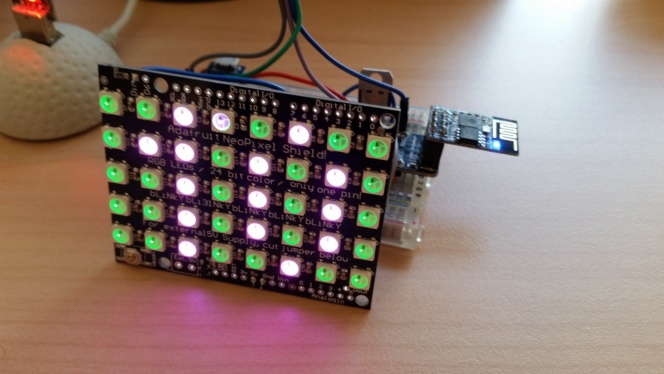
The example project to which I link in the end of this blog will signal the battery voltage level by blinking a led several times every 10 seconds. Each blink represents 0.1V over the 2.0V base voltage. So 7 blinks means we have a battery voltage of 2.7V.

How long will this project run from batteries? Let's calculate an approximation:

In sleep mode my attiny84 uses 0.004mA. When calculating it uses about 20mA, but it is sleeping most of the time. Running at 8MHz it will only execute code for about 1ms every 10 seconds, so it's average contribution to the power usage is 20/10000= 0.2mA.

The led draws about 3mA when lit. You can measure the current by reading the voltage over the led serie resistor: 1.0V over 330ohm. It blinks 7 times for 125ms every 10s, so it contributes about 7*125/10000*3= 0.26mA on average.

Total average usage is about 0.3 (led) + 0.2 (micro controller)= 0.5mA. A 2000mAh battery will result in 2000/0.5= 4000h battery time, that is about half a year. Note that you should use low discharge NiMH cells (the pre-charged variety) or normal alkaline cells for long running low power applications. If you use solar charging then self discharge is not an issue.

If your project is more power hungry and runs only for a few weeks from a set of batteries, then a solar powered solution makes really sense. Another reason to use solar power is when the application is on a location where changing batteries is difficult.

Charging NiMH batteries

is in general hard when you want to do it optimally. For a start, you cannot charge cells in series reliably. A good NiMH charger will charge each cell individually, because they tend to get out of sync after a while. It's a good idea to charge the cells in a good charger before using them in your attiny project, and e.g. once in a year. For the same reason you should use identical cells of the same make and previous usage. Don't worry too much about these aspects, in reality your solar powered project will run just fine.

Over charging and trickle loading

Over charging NiMH batteries should be prevented. A simple way is to just use a low charge current over a long time. A C/20 current which is interrupted every 12 hours (because it gets dark :-) or a C/40 24 hour constant current (trickle charging) is absolutely safe. For 2000mAh cells this means 100mA or 50mA. Now the good news! You'll have to buy quite a big solar panel to risk over charging your batteries. Just use a small one which compensates the average power usage of your project. Measure charge current during sunny periods and you should be happy if you exceed 100mA or even 50mA. Our example project uses about 12mAh in a day. An average of 15 minutes of 50mA sun charge each day will keep your cells full. So no need to worry about over charging or too less charge capacity in general. If you measure about 2.7V over your two cells then they are fully charged. 2.8V means you're charging. Over 2.9V means that you are charging quite fast. In the latter case measure charge current and consider using a charge current limiter. The cheapest way is to use a smaller solar panel.

The Solar Panel

I used two small 4V/40mA panels in series:

3V is an absolute minimum if you want to get any charge current into your two NiMH cells in series. The cells have 2.4V when they are not full. The dark current diode has a 0.3V forward drop when you use a germanium or Schottky diode, so charging starts at 2.7V. It will start at 3.1V if you use a normal silicon diode which has a forward drop of 0.7V.

Note that the voltage/current specifications of panels are in very bright sunshine. If you need to charge in low light environments then it's better to use a panel which has a voltage specification well over 3V.

If you use a solar panel which provides over 5.5V then you should take care that you do not disconnect the NiMH cells in bright light. The connected NiMH cells will prevent a high voltage, but when they are disconnected the voltage provided by the solar cells may rise over 5.5V and your attiny chip may be damaged. You can add a 5.6V zener diode to prevent damage.

The schema and other components

I've already mentioned the diode which prevents a discharge of the NiMH cells over the solar panel when it's dark. You can use any diode, but for optimal power efficiency you could use a germanium or Schottky diode.

In order to measure the NiMH voltage with the attiny ADC we use a voltage divider composed of two resistors. The attiny has an internal reference voltage of 1.1V, so we cannot measure voltages over 1.1V. The two resistors (1MOhm and 330kOhm) in series divide the voltage approximately by 4, so we'll be able to measure 0 - 4.4V. If you use 4 cells in series then replace the 330kOhm by e.g. 220kOhm, so you can measure up to 6.1V. I used large resistors so that the current loss is very small, less than 3uA. In my example code, get it here from github, I calibrated the resistors and 1.1V reference voltage by measuring the voltage on the ADC input. Note that the 100nF capacitor between the ADC input and ground is really needed to eliminate high frequency noise on the ADC input. Without it your ADC measurements will be all over the place. I also added a capacitor over Vcc and GND just to be safe.

I tested with a power supply of 3.43V. The ADC returns a value in the range 0 - 1023. The expected ADC value would be:

330/(1000+330) * 3.43 / 1.1 * 1024 = 792

I got 775, a 1.5% error, not too bad considering the 5% resistors I used.

How to proceed from here

Now that I have a stable base platform I plan to use it as a remote wireless sensor. I'll be adding a radio transmitter (eg a Bluetooth slave which you already see on the bread board) to send temperature and barometric pressure info to my server. The goal is to intercept this info from a commercial 433Mhz outdoor weather station. Its data will be added to the graph (from another Arduino project) which shows current temperature and humidity in my work room:

The transmitter will need more than 2.7V so I'll either use a DC/DC converter or switch to 4 NiMH cells, but more about that in another blog entry...

Powering a normal Arduino

In this blog entry I described powering an attiny from 2 NiMH cells. The principle is easy to adapt to normal Arduinos. Just use 4 NiMH cells in series (results in 4.8 - 5.5V voltage) and connect it with a diode to a small solar panel which supplies at least 6V when the sun shines. That's all.

You can monitor the charge voltage or (charge) current with a cheap multimeter and check that all is fine. Connect your normal arduino to the NiMH cells and it will run just fine.

If you want to connect the NiMH cells to the power regulator input of the Arduino then you'll have to add more cells for a higher voltage (at least 6V) if you really want to run the Arduino at 5V, but you'll waste some (solar) power. Arduinos will not really need the full 5.0V (except the original atmega8) when they run at 16Mhz, so you can safely use the regulator. As a side effect the Arduino will draw less current because the voltage is now lower. Compared to a standalone attiny the Arduino power led and support circuits will always waste energy, but if your solar panel is not too small it will keep running.

Some measured data:

4 NiMH cells connected to unregulated 5V pin: 45mA current due to led and not in sleep mode.

NiMH connected on regulated Vin pin: 34mA current due to led and not in sleep mode. The 5V pin is now on 4.3V while the 4 NiMH cells provide 5.25V. At this rate (34mA) you'll need to charge every other day, so a solar based charger really makes sense.

Arduino in sleep mode in above setup: I estimate that it will use less than 5mA. This means that a normal Arduino might run a few weeks on 4 charged NiMH cells, and adding a small solar panel will extend this to ever.